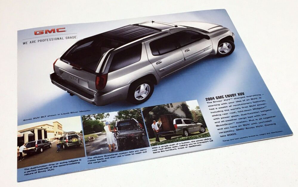
Figure 1, GMC XUV
Everyone wants everything fast today. Products and services that continuously flow through your business achieve the speed needed to beat the competition to the punch.
Water flowing through a network of pipes is a good way to think about your product and information flows. Current state flows typically have big interruptions throughout the process where inventory and backlog build up – as shown at the bottom of the figure. As a result, lead times are long and highly variable, making it difficult to predict when a customer will get their product/service. Consequently, a heavy burden is placed on your team to constantly adjust schedules and plans.
The first goal is to create flow with designed interruptions such as inventory stores, queues and staging areas. These countermeasures provide design and stability to the business, as illustrated by the middle flow in the figure. From this state of relative stability, it may be possible to remove some of the designed inventories as processes are improved. This results in a more continuous flow that drives superior quality, lower costs and faster delivery.
GMC introduced a new SUV model in 2004 that had a retractable rear roof section. It was called the GMC XUV, see Figure 1 above. It allowed the SUV to function as an open bed truck when needed.
Alcoa made the aluminum rails that the roof slid on when retracting. Figures 2 and 3 below show the left and right rail sets. The business making these rails was having trouble with quality, capacity and flow time through the manufacturing cell. One of the areas we worked on was flow simplification to increase capacity and improve quality. The results of the project yielded a 80% reduction in quality reject rate and a 50% improvement in capacity and material flow time.
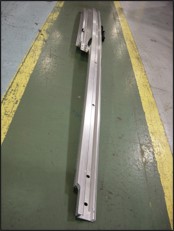
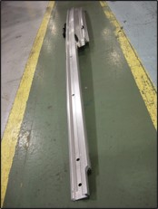
Figure 2, Left Rail
Figure 3, Right Rail
Figure 4 shows how each step in the process changed the parts. It starts with 2 parts (long and short), that are assembled together to make 1 part, bent to match the contour of the roof, then cut in half to make the left and right-side roof rail sets. From there miscellaneous machining is done to add the product feature such as mounting locators.
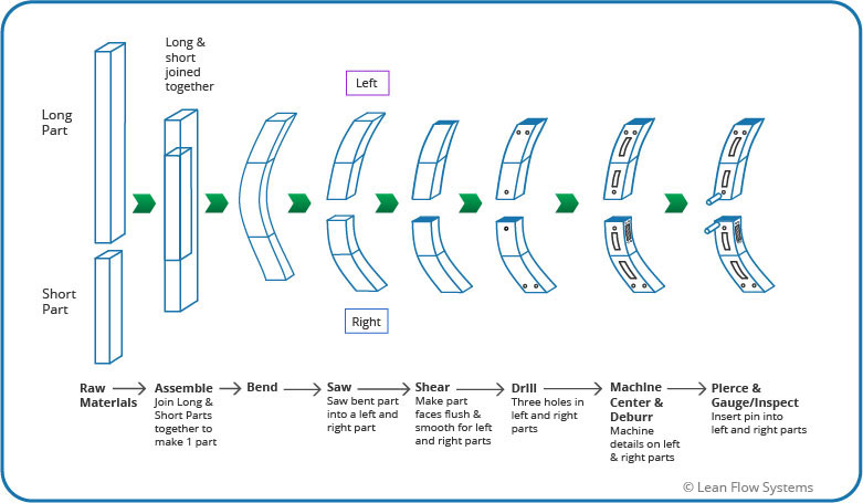
Figure 4, Component Processing Steps
Figure 5 below shows the original and improved material flows. In the original complex flow, the left and right rails ran on any of the machines at each step in the process, causing complexity, confusion and delays in flow as parts waited at every step. Problems found in inspection were hard to solve to root because the issues were often machine-dependent. It was taking extra time and energy to discover which machines a problem part had run on.
We simplified the flow as shown at the bottom of Figure 5. After Saw, the left and right parts had their own set of dedicated machines to run on. This streamlined process was fast, efficient and made problem solving much easier.
However, there was one big problem we needed to solve. In the current state complex flow, three machine centers were required to have enough capacity for the product. This was a problem because one Machine Center would have to be shared between the two lines, thus complicating flow. To resolve this challenge we ran a Machine Kaizen Event. This event revealed a number of opportunities to increase capacity on the Machine Centers:
We made improvements to address these problems and were able to get enough capacity to only need one Machine Center per flow line. The third machine center was sidelined for use on other products, thus saving capital equipment investment.
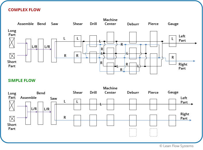
Figure 5, Complex vs Simple Flow